BIM Linear Solid
Commands: BimLinearSolid, BimApplyProfile, BimProfiles
Overview: In this lesson, you learn how to use the Linear Solid tool to create structural members and flow segments.
Lesson Objectives
After completing this lesson, you will be able to:
- Use different structural member profiles and piping profiles in your structural and mechanical modeling.
- Apply and replace profiles of linear solids.
- Add eccentricity to linear solids.
- Recalculate the axis of linear building elements.
- Make structural connections and flow fittings.
About BIM Linear Solid
The Linear Solid tool allows you to create structural members or flow segments. The tool can be made use of creating a variety of structural member profiles or MEP elements.
![]()
For more information about this command, visit the Command Reference article BimLinearSolid.
For more information about MEP modeling, visit the help article MEP Modeling and MEP Flow Connection Points.
Creating a single linear solid
Tutorial: How to use linear solids
Click here to watch
Before starting the process, make sure that Quad is active. Next, follow these steps:
- Hover over the Model tab in the Quad and select the Linear Solid tool.
You are prompted: Set start point or [Follow/Rectangular/Circular/Dialog/select in Model/adJust profile] <Last point>:
- Select a start point.
You are prompted: Set next point or [Angle/Length/Undo/Quarter turn/Rotate/choose other Profile/adJust profile]:
- Move the mouse cursor to draw the beam or column.
- Click to specify the endpoint, or enter a value for the distance using the dynamic dimension field.
- Press Enter key to accept it.
The following illustration shows a beam and two columns with the default rectangular profile.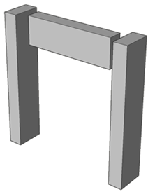
About BIM Profiles
Tutorial: How to use the Profile Library for linear solids
Click here to watch
BIM Profiles toolbar
You can access the BIM profiles panel by clicking the I-beam on the right-hand side of your screen. If the BIM Profiles toolbar is not displayed on the right-hand side of your screen, right-click on the Tool Panel at the right-hand side of your screen, then choose BIM Profiles in the context menu.
Note: You can also find the BIM Profiles Panel by typing BIMPROFILES in the commandline.
The following illustration shows the BIM Profiles Panel.
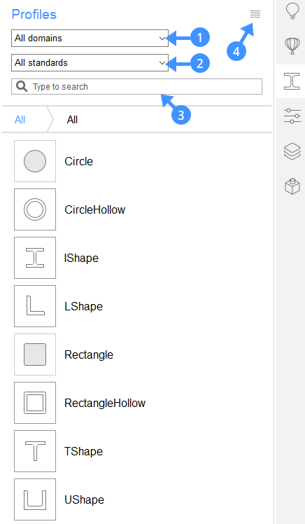
The drop-down box at the top (1) acts as a filter. There are different domains on which you can filter: Generic, Structural Concrete, Structural Steel, HVAC, Piping and Electrical.
Note: If you don't have any profiles in a certain domain, you will not be able to filter on it.
The second drop-down boxes (2) allow you to filter the profiles by the country standards.
The search box (3) allows you to filter by name.
The menu (4) on the right-hand side allows you to access the BIM Profiles dialog box. Clicking the menu icon displays a context menu with a couple of options.
The following illustration shows the BIM Profiles context menu.
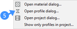
Select Open profile dialog (5) on the menu to open the Profiles Dialog box.
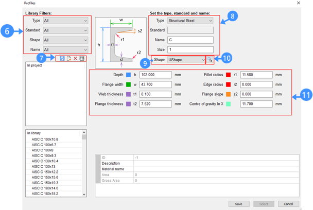
The following illustration shows the Profiles dialog box.
|
Filters (6) |
Filters the profiles list by:
|
|
Tools (7) |
|
|
Custom fields (8) |
Set the type, standard, name, and size of a profile |
|
Preselect shape (9) |
Select a shape from the drop-down list |
|
Pick profile in model (10) |
Select a closed 2D entity or the boundary entities of an enclosed area |
|
Profile properties (11) |
Shows the properties of the selected profile |
About BIM Apply Profile
The Apply Profile tool allows you to change the profile of linear entities and linear solids. Linear solids have a constant cross-section over a linear extrusion path. The tool recognizes clippings and openings. Using the Apply Profile tool, you can create columns, railings, beams, pipes, ducts and more.

For more information about this command, visit the Command Reference article BimApplyProfile.
Applying profile to linear solids
- Launch the Apply Profile tool.
- Select a linear entity or linear solid in the drawing area.
You are prompted: Select profile [in Dialog] <in Dialog>:
- Type ‘D’ in the command line or click ‘in Dialog’ option on the prompt menu to open the Profiles dialog box.
Use the Filters section to sort the profile by type, standard, shape or name.
Choose one of the available profiles in the library.
Or pick a profile in the model to create a custom shape profile.
Click the Pick profile in Model button in the dialog box and select an existing profile in the drawing area.
- Press Enter to accept changes.
About BIM Add Eccentricity
BIM Add Eccentricity allows you to control the relative position of the axis of a linear solid.

For more information about this command, visit the Command Reference article BimAddEccentricity.
Add eccentricity to linear solids
Tutorial: How to add eccentricities to linear solids
Click here to watch
- Select an existing linear solid in the drawing area.
- Initiate the Add Eccentricity tool.
The eccentricity widget appears with the possible locations.
- To set an eccentricity, click one of the nine locations from the widget, then right-click to confirm.
- Optionally, type a location in the command line.
The options of the locations are: TR: Top Right, TM: Top Middle, TL: Top Left, MR: Middle Right, C: Center (resets the axes of the selection set to the default location), ML: Middle Left, BR: Bottom Right, BM: Bottom Middle, BL: Bottom left
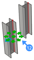
- Press Enter to accept changes. The following illustration shows the Eccentricity widget (12) on the linear solid profile.
About BIM Recalculate Axis
The Recalculate Axis tool recalculates the axis of linear building elements and repositions it back to the centerline of a linear element.

For more information about this command, visit the Command Reference article BimRecalculateAxis.
Recalculate the axis of linear building elements
-
Select any linear building element in your model
-
Initiate the Recalculate Axis tool
-
The axis of the element is moved to the default position.
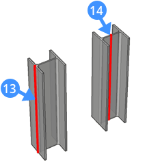
The following illustration shows the result of using BIM recalculate axis on the linear solid. The axis (13) is moved to the centerline (14) of the linear element.
About the Structural Connect Tool
The BIM Connect tool can be used to connect linear solids. It makes a connection between the selected linear solids with the option of smooth or planar cuts.
![]()
For more information about this command, visit the Command Reference article BimStructuralConnect.
Making a structural connection to linear solids
Tutorial: How to connect linear solids
Click here to watch
- Select the linear solids that need to be connected
- Initiate the Connect tool
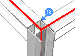
- The Hotkey Assistant appears at the bottom of the screen to remind you of different options. The following illustration shows the BimConnect tips widget. The default connection type is indicated by a blue frame.
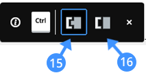
Smooth cut (15)
One solid is fully extended to connect to all the other solid’s faces Planar cut (16)
Solids are cut with straight planar cuts Press the CTRL-key to cycle through the connection options.
- Select one of the connection options and press Enter to accept the connection.
The following illustration shows the smooth cut (17) and planar cut (18) on an existing structural model.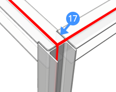
0 Comments